Active scanning
Table of contents
Structured light
Structured light methods are actively projecting light patterns onto the scene, creating features that are easily detected by one or more cameras looking at it.
Laser line
A straightforward to introduce structured light to the scene is to project a line using a laser:
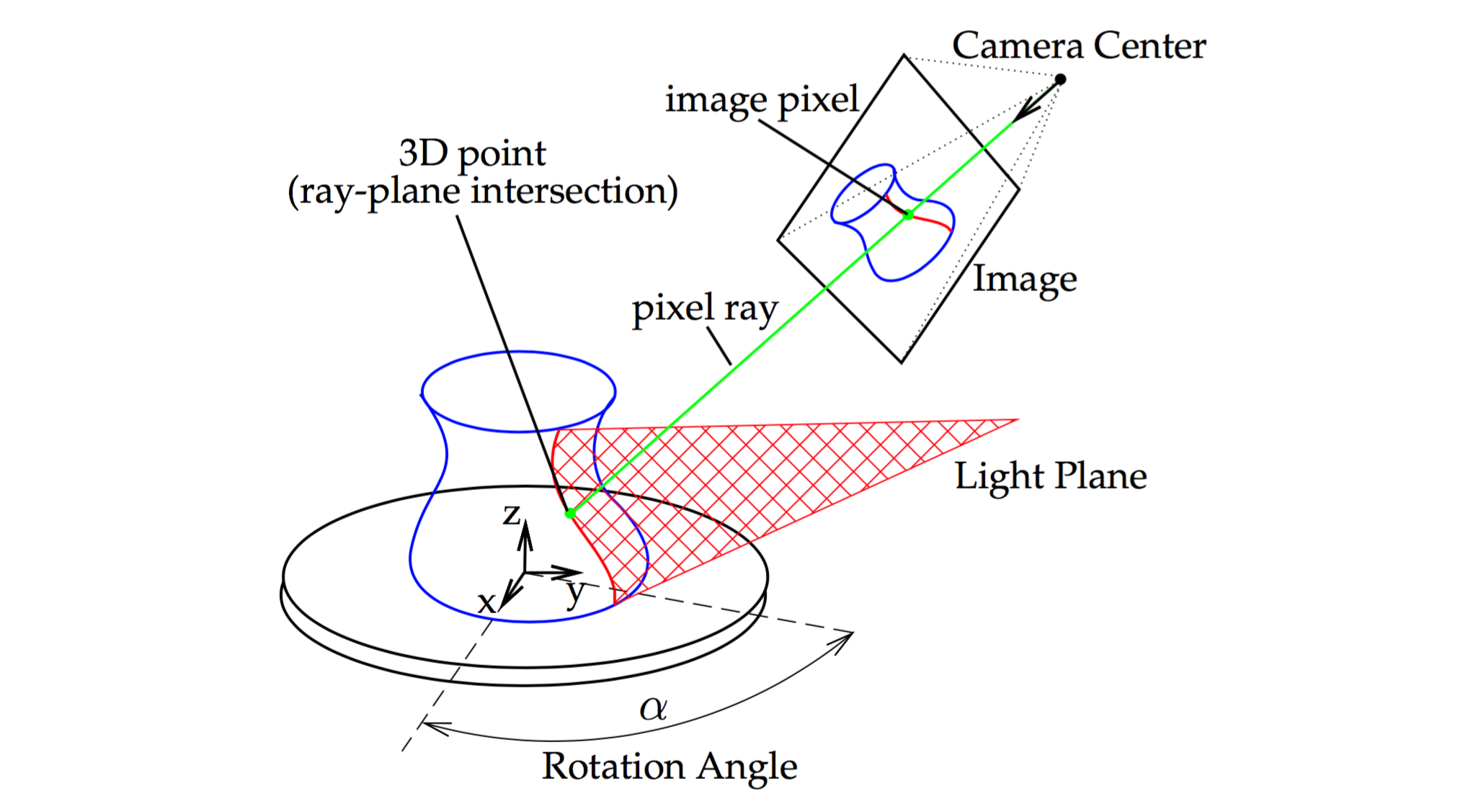
source: http://mesh.brown.edu/desktop3dscan/ch4-slit.html
The illuminated pixels are easily detected on the camera. For each illuminated pixel, the camera’s intrinsic and extrinsic parameters can be used to obtain the cartesian equation a line on which the 3D point must lie. If the laser’s plane cartesian equation is known through prior calibration, the intersection between that plane and the light ray is straightforward to compute.
After collecting 3D coordinates of each point on the illuminated curve, the object is moved or rotated, and more points are accumulated. Note that the rotation of the object must be precisely known in order to place the 3D points in the right context. In other words, the camera’s extrinsic parameters must be accurately updated for each object pose.
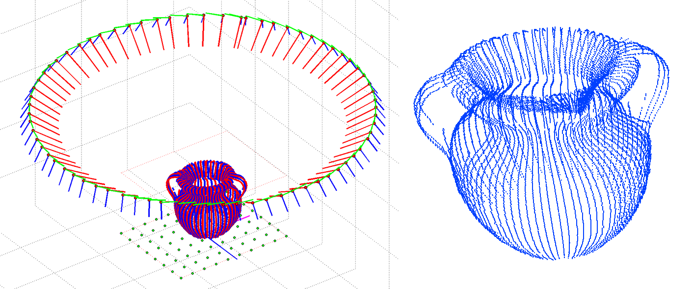
source: http://mesh.brown.edu/desktop3dscan/ch4-slit.html
Encoded pattern
Projectors are a bit like reverse cameras: they use optics to project light rays onto the scene, rather than sensing them. The camera equations we previously presented are just as valid for projectors, and can be calibrated in a similar way. This also implies that the stereo vision principles can be applied to a projector/camera pair, rather than a camera/camera pair.
In projector-assisted structured light methods, easily detectable features are projected onto the scene, to be then detected by the camera and triangulated back to a 3D coordinate.
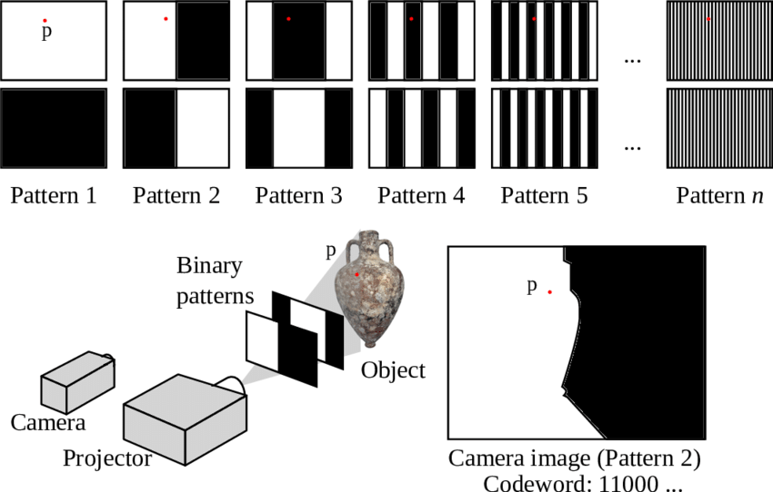
There is a multitude of options for the projected pattern, but an interesting strategy is to project successive binary stripes. After each exposure, an additional bit is detected by the camera, until the finest grain achievable by the projector. This reveals a binary code in each pixel of the camera, univocally linking it to a part of the projector’s pixel coordinate system.
Using binary encoding reduces the number of required exposures from $w$ to $\lceil\log_2(w)\rceil$, with $w$ being the projector’s horizontal resolution.
Uniquely identifying a pixel column of the projector is sufficient: triangulation can then be made with the same method we previously described for laser line systems. Alternatively, a succession of horizontal and vertical binary encodings can be used to uniquely identify each individual pixel of the projector.
Pseudo-random pattern
Instead of using a projector that can display arbitrary patterns onto the scene, another approach is to use a pseudo-random pattern projected by a simple filter placed in front of a light source.
The pattern is carefully chosen to not have self-similarity, letting the camera uniquely identify and locate its patterns. The features can then be triangulated, assuming the projector’s pattern projection geometry was calibrated beforehand.

The Microsoft Kinect V1 was using this principle. While this is a cost-effective approach, it leads to very poor resolution, as the granularity of details is ultimately limited by the feature size present in the pattern.
Time-of-Flight
LiDAR
In LiDAR, a laser pulse is sent and bounced back to the sensor. A detected pulse provides a distance measurement in the laser direction. To obtain a full 3D map of the surrounding, the laser needs to rotate to cover a wide variety of angles. The density can be tuned at the expense of a longer capture time.

LiDAR has become popular in the car industry, as it is reliable at long range too and is not subject to interference from sunlight. The other main application is architectural scanning, for which the accuracy is far sufficient. In this case, it is often necessary to combine scans from several locations. This creates visible viewing rays in the point cloud distribution.
ToF cameras
A time-of-Flight camera is similar to a LiDAR setup with a single emitter and millions of receiver: each is implemented as a CMOS pixel with a demodulator. In this case, we don’t use pulses but rather modulate an IR LED with a sine-like profile. This lets the pixels estimate the phase shift of the received sine-wave.
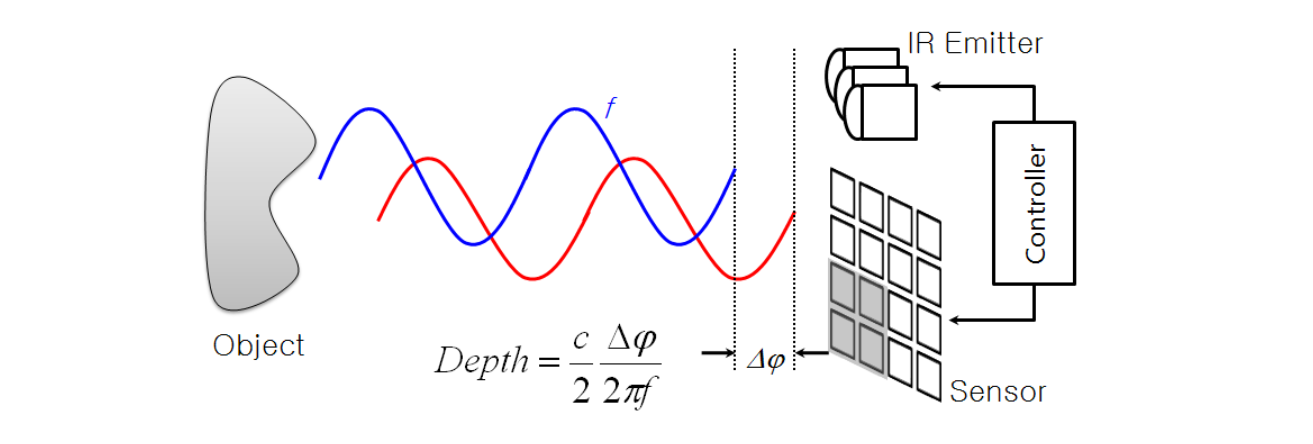
The phase shift can be measured in several ways, but is typically obtained from 4 amplitude measurements. The strength of the signal is also retrieved, which is important for noise estimation.
ToF cameras are popular in gaming and realtime applications as they provide a depth map in a single capture, up to 1024x1024 pixels for the Kinect V4 sensor.
One common issue for complex scenes is multipath, where the IR light bounces from a second object before returning to the sensor. This typically produces rounded corners with loss of details. Another issue is flying pixel, occuring on edge regions (mixing of foreground and background signals).
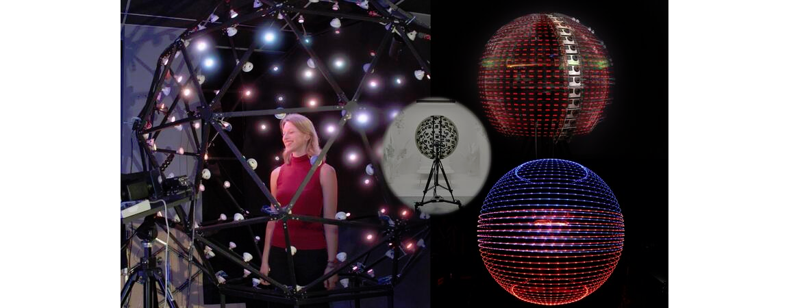
Light Stage
This impressive device was built for capturing the Bidirectional Reflectance Distribution Function (BRDF), which can describe the material’s optical properties in any direction and any illumination conditions. Thanks to the linearity of lighting, we can decompose the total illumination based on its direction. The viewing angle also plays a role for reflective or special materials (e.g. iridescence).
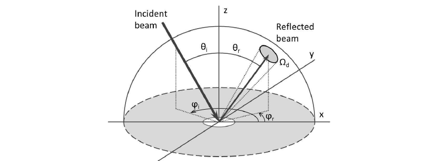
In the most complex case, objects need to be captured from several locations and illuminated from as many directions as possible.